Experiment Password
This is a virtual simulation of the Statics Practical. In this simulation, you will examine the balance of torques on a static beam. A movable and variable load is added to the beam to change the torque about the pivot. The total clockwise torque about the pivot is due to the load and the weight of the beam itself.
Opposing the clockwise torque about the pivot is a torque supplied by the tension in a wire attachced to one end of the beam. The wire runs from the beam over a pulley to a stretched spring which provides the tension. The adjustable pivot, where the beam attaches to the stand, allows the beam to be moved up and down. This will modify the torque applied to the beam by the wire.
During this practical, you will:
- Calibrate the spring by creating a graph of spring length vs applied weight
- Determine the negative torques due to the load and the beam
- Determine the positive torques due to the tenshioned wire
- Show that the positive and negative torques are equal when the system is in equilibrium
- Make measurements of the torques and plot the results for two different settings of the apparatus
Calibrating the Spring
An ideal spring follows Hooke's Law where the force:
\( F = -kx \)
Where \(F\) is the force due to the spring, \(x\) is the extension of the spring, and \(k\) is the spring constant which must be determined through a calibration experiment. The negative sign reflects the fact the force generated is in the opposite direction to the extension or compression. In the statis practical, the spring will be stretched, thereby providing a tension in the wire.
In this virtual practical, you are lucky enough to have an ideal spring so Hooke's Law will apply exactly. In the real lab with a real spring, the linear approximation of the relationship between the force and the extension may not apply.
In either case, you will hve to make a number of measurements with the apparatus, set up to measure spring extension vs. load.
First, we set the apparatus up as shown in the following diagram:
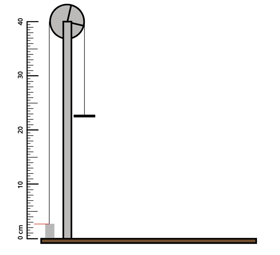
This is done in the lab by swinging the beam out of the way and rethreading the wire over the pulley so that the load hangs directly off of it.
Second, remove the load and measure the length of the spring – tgis will be the zero point for your calibration measurements. In principle it shouldn't matter where you measure the spring from as long as you always use the same spot, in practice it is best to choose a reference point somewhere above the spring, probably on the wire itself.
In this virtual practical, the reference point is just above the spring and indicated by a red line. Different loads are hung on the wire and the length of the spring is recorded.
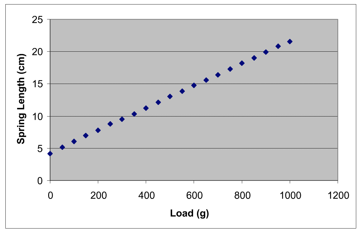
A plot of spring length vs. load will show a roughly linear relationship. You will use the plot to determine the tension supplied to the wire by the spring in the final experiment.
Note: your measurements will probably differ from this example!
Measuring the Negative Torques
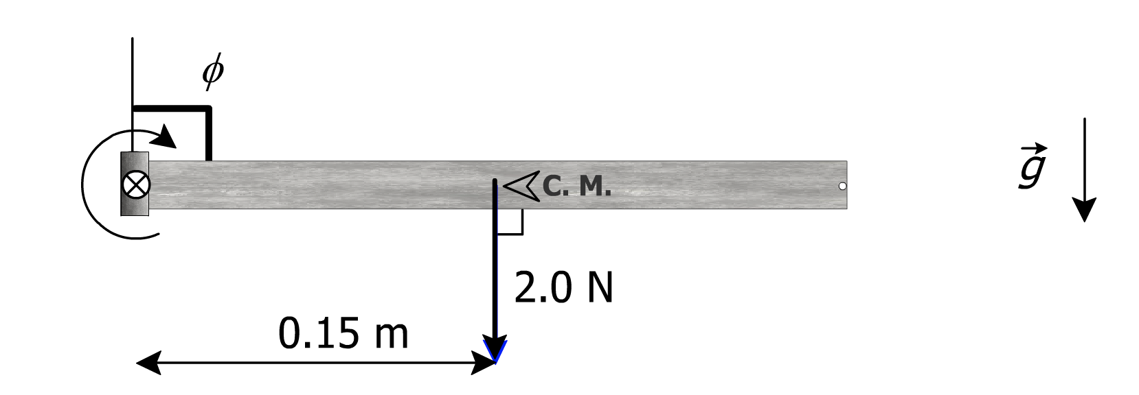
The negative torques in this experiment are the torques on the beam around the pivot point, due to the weight and the load hung on the beam. These torques are considered negative because with the beam appataratus set up with the spring on the left-hand side (as presented in this virtual practical) these torques are in the clockwise sense, and so, generate a negative torque (direction: into screen).
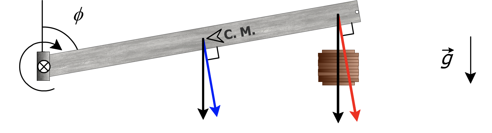
The first torque is the torque due to the weight of the beam (the black arrow) times the level arm relative to the pivot. This torque arises from the component of the vertically directed weight of the beam, through the centre of mass of the beam, acting perpendicular to the beam (the blue arrow)
If the beam is horizontal, then the calculation is simple. The magnitude of the first torque is just the distance between the centre of mass and the pivot point (0.15 m) multiplied by the weight of the beam, or:
\( 0.20kg * g = 2.0 N \)
Where \(g\) is acceleration due to gravity,
or \(9.81m/s^2\)
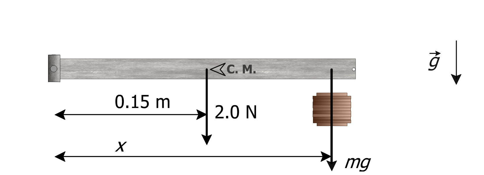
The second torque is due to the weight of the load, \(m\), that you will hang on the beam. You will control the magnitude of the load, and the location it is placed; in general the magnitude of the second torque will not be the same as the first torque.
Again, as long as the beam remains horizontal, calculation of the torque is easy. Just take the distance from the pivot to the load, \(x\), and multiply by the total weight, \(mg\).
The two torques can be simply added, so that we can write a general expression for the negative torque acting on the beam:
\(\Sigma \tau _{-} = (2.0 N)(0.15 m) + (mg)x\)
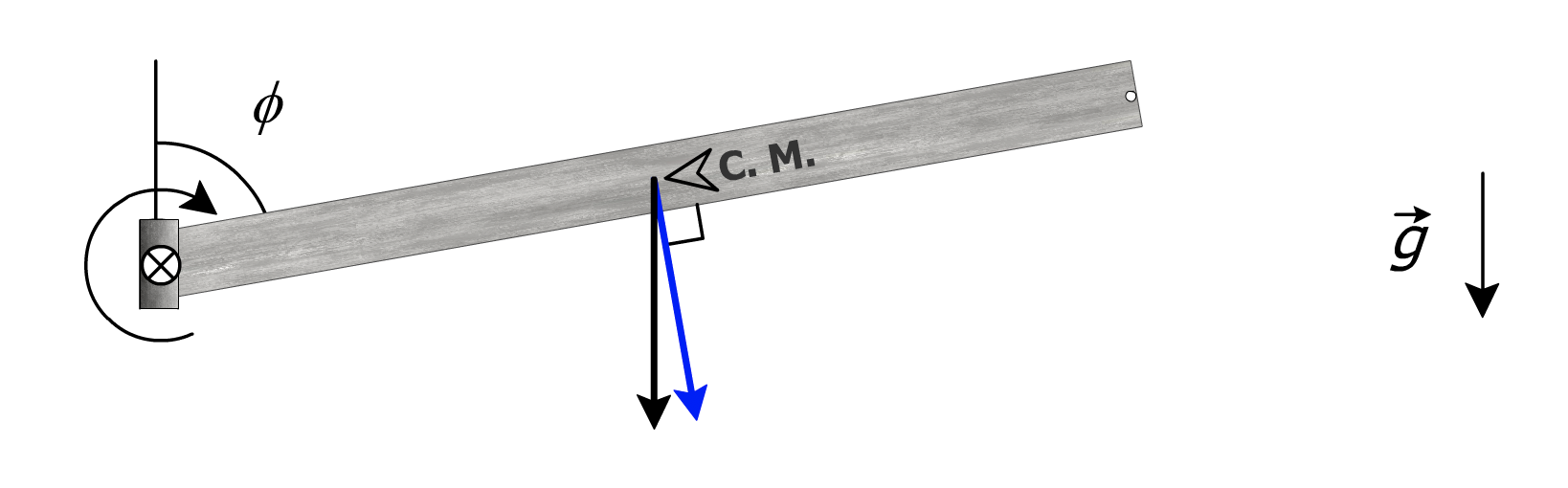
Because the beam is perpendicular to the gravitational acceleration, the forces applied to the beam by both the load and the mass of the beam are automatically perpendicular to the beam. This makes the negative torque calculation much simpler. We will take advantage of this in the practical by trying to arrange for the beam to be as horizontal as possible during the measurements.
In the online practical, you'll be able to check the angle of the beam by turning on the protractor using the relevent button, producing a protractor overlay at the pivot end of the beam. The protractor button will also turn on a digital displace that will indicate the angle the beam makes with the stand to within 1°. Note, you may not be able to get exactly 90° for every combination of load and pivot height, think about how this will affect your final calculations.
Measuring the Positive Torques
The positive torque on the beam is supplied by the tension, \(T\), in the wire that runs from the spring to the right hand tip of the beam. Because the tension acts at an angle, \( \theta \), to the beam, we will need to calculate the normal component of the tension (\( T sin\theta \)) to find the torque.
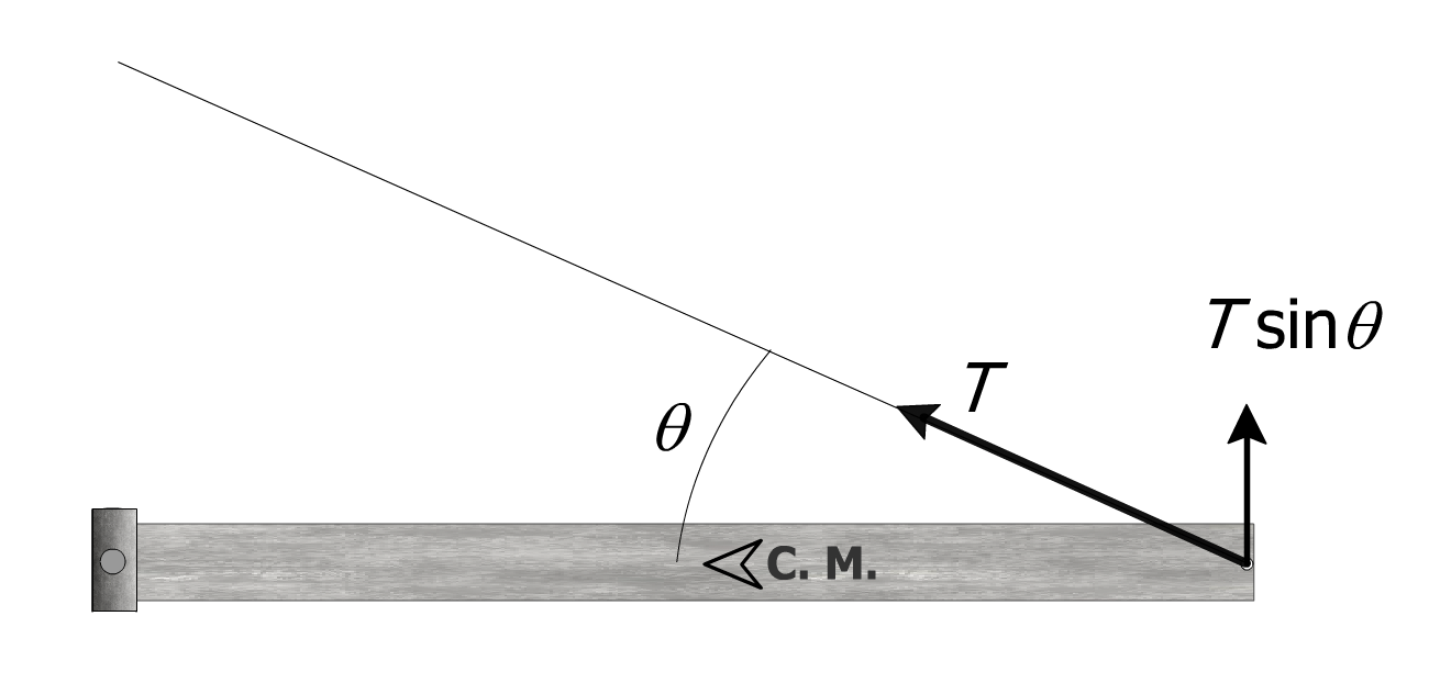
The torque is then \(Tsin\theta \) times the length of the beam. The length of the beam is nominally 30cm, but we will refer to it as \(L\) for now in anticipation of a little trick we'll use later on. The positive torque is then:
\(\Sigma \tau _{+} = Tsin\theta L \)
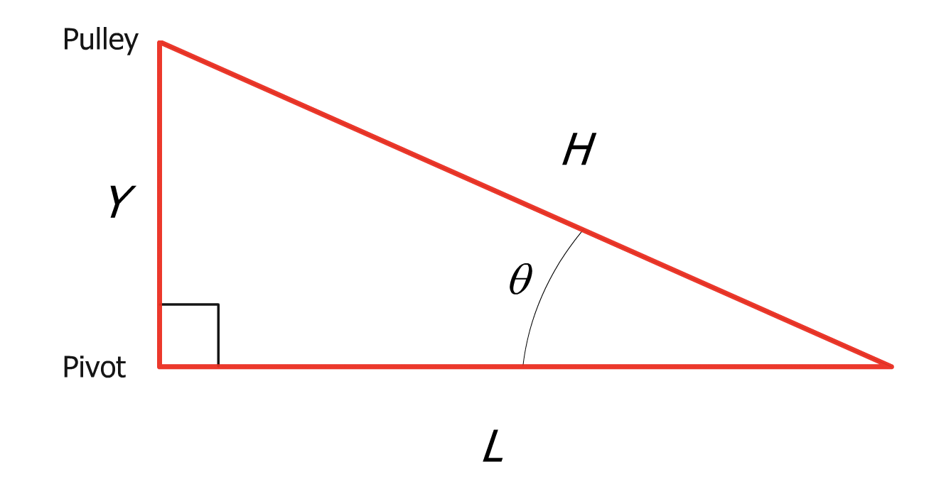
The value of \(T\) will be determined by observing the spring displacement and using the calibration plot to estimate the tension in the wire. To find \(sin\theta\) you will need to measure parts of the triangle created by the wire (\(H\)), the beam (\(L\)), and the stand (\(Y\)).
One Method: Finding \(\sin\theta\)
One way of getting \(sin\theta\) is to measure \(Y\) and \(H\) directly. This involves two measurements and there will be uncertainty in each of the measurements.
\(sin\theta = {Y\over H} \)
Another method: Finding \(\theta\) directly
Finding \(theta\) directly from the inerse tangent is another possible method, this involves only one measurement of \(Y\), and two uncertainties, the uncertainty in \(Y\) and a small uncertainty in \(L\).
\(\theta = tan^-1 {Y\over L} \)
One more method: Using \(L\) as a hypotenuse
However, we can eliminate \(L\) in the positive torque equation all together by creating a triangle in which \(L\) is the hypotenuse.
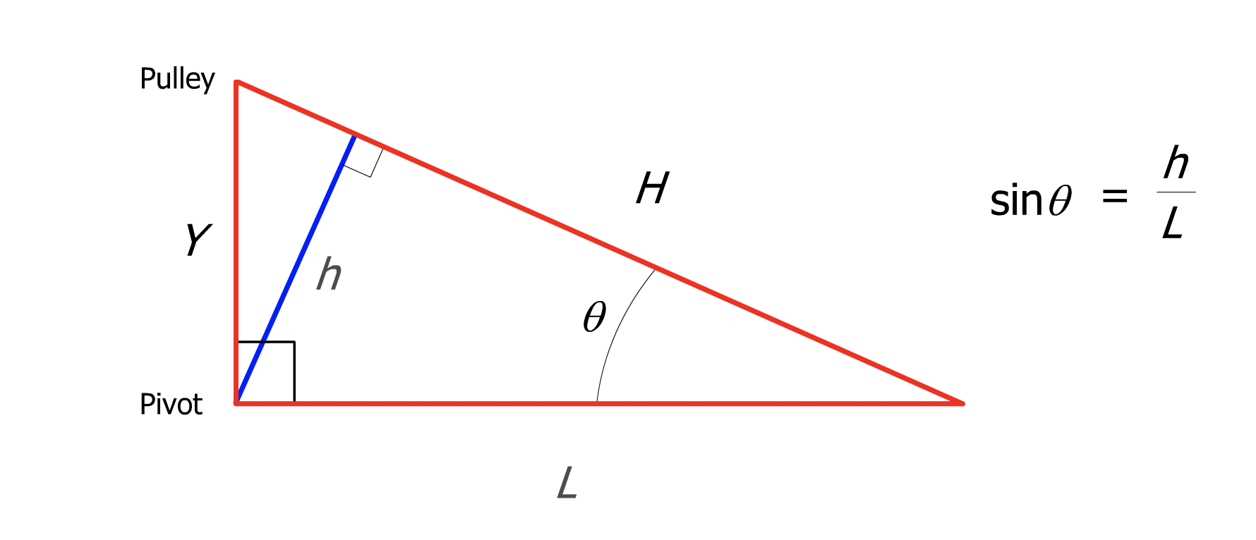
\(sin\theta = {h \over L} \)
\(L\) cancels out entirely and the positive torque is simply the string tension times the perpendicular measurement. This method requires only the one measurement of (\h\).
\(\Sigma \tau _{+} = T h \)
To measure \(h\) in this online practical, you are provided with a ruler that can be turned on by using the ruler button. This ruler will automatically adjust to be perpendicular to \(H\). In the laboratory practical, you will have to do this yourself.
Show Positive and Negative Torques are Equal
The results of your calculations should show that the positive and negative torques are equal, any discrepency will be due to experimental uncertainties.
Possible sources of uncertainty in this experiment:
- The length of the beam (this will affect cetre of mass calculations too!)
- The mass of the beam and the pivot height
- The mass and position of the load
- The exact angle the beam makes with the stand
- Any measurement made with rulers (they are all finite precision)
Note: The random parameters within the experiment depend on the password generated at the start of this practical. If you refresh the page and get a new password, your parameters would also be different.
The password generated for this practical was:
Take Second Measurements
After measuring one set of torques, change the load and the pivot height to get a second set of troques. Plot your results for both pairs of positive and negative torques on an x-y plot with positive torques on one axis and negative torques on the other.
If the clockwise and anti-clockwise torques you have calculated are equal then you should be able to fit the data to a theory curve with a slope of one that goes through the origin (why?). If your data do not, you will need to explain why not.
The virtual practical tools start on the next page.
Before you start: To get separate points on your plot, you have to vary the magnitude of the torques. To do this, you will need to change the pivot height between measurements. If you only adjust the magnitude and location of the mass along the beam, keeping the pivot height constant and the beam horizontal, you are essentially keeping the torque on the beam the same for each configuration.
If you do not plot your data as you collect it, then at the end of the 3-hour practical, when you come to plot your data, you will find all your data points lie approximately on top of one another and you will not be able to find a line of best fit!
This can be very frustrating, and illustrates one very good reason why we suggest that at least one person in your group should graph your torques as you calculate them rather than waiting until all the data is collected.
Load (g): 150
The weight and positioning weren't balanced and the weights or bar hit the ground or apparatus. Try changing the variables again.
Load (g): 150
Load Position (cm): 15
Pivot Height (cm): 20
Phi